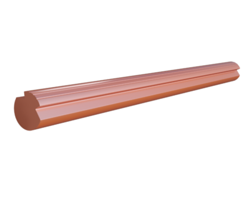
Contact Wire (Cu-Ag/Cu-Sn/Cu-Mg Alloy)for Electrified Railway
The drawing stock or intermediate rod stock is a copper or copper silver as defined in standard EN 1977 or a copper cadmium, copper magnesium or copper tin alloy.
| Material | Nominal Cross Section | Designation | Max. resistance at 20 °C |
Min. Breaking Load | Mass | Percentage elongation after Fracture A200 | Min. Tensile Strength |
||
| mm² | Ω/km | kN | Min. kg/km |
Max. kg/km |
Min. % |
Max. % |
N/mm² | ||
| Normal Strength Copper | 80 | Cu-ETP Cu-FRHC Cu-HCP Cu-OF |
0.229 | 27.5 | 690 | 733 | 3 | 10 | 355 |
| 100 | 0.183 | 34.5 | 862 | 916 | 3 | 10 | 355 | ||
| 107 | 0.171 | 36.3 | 923 | 980 | 3 | 10 | 350 | ||
| 120 | 0.153 | 38.4 | 1035 | 1099 | 3 | 10 | 330 | ||
| 150 | 0.122 | 45.1 | 1293 | 1374 | 3 | 10 | 310 | ||
| High strength Copper and high strength Copper-silver Alloy | 80 | Cu-ETP Cu-FRHC Cu-HCP Cu-OF Cu-Ag 0.1 |
0.229 | 29.1 | 690 | 733 | 3 | 8 | 375 |
| 100 | 0.183 | 36.4 | 862 | 916 | 3 | 8 | 375 | ||
| 107 | 0.171 | 37.4 | 923 | 980 | 3 | 8 | 360 | ||
| 120 | 0.153 | 41.9 | 1035 | 1099 | 3 | 8 | 360 | ||
| 150 | 0.122 | 52.2 | 1293 | 1374 | 3 | 8 | 360 | ||
| Normal Strength Copper-silver Alloy | 80 | Cu-Ag 0.1 | 0.229 | 28.3 | 690 | 733 | 3 | 10 | 365 |
| 100 | 0.183 | 34.9 | 862 | 916 | 3 | 10 | 360 | ||
| 107 | 0.171 | 36.3 | 923 | 980 | 3 | 10 | 350 | ||
| 120 | 0.153 | 40.7 | 1035 | 1099 | 3 | 10 | 350 | ||
| 150 | 0.122 | 50.9 | 1293 | 1374 | 3 | 10 | 350 | ||
| Copper-magnesium alloy | 80 | Cu-Mg 0.2 | 0.289 | 35.7 | 690 | 733 | 3 | 10 | 460 |
| 100 | 0.231 | 43.7 | 862 | 916 | 3 | 10 | 450 | ||
| 107 | 0.216 | 45.7 | 923 | 980 | 3 | 10 | 440 | ||
| 120 | 0.192 | 50.1 | 1035 | 1099 | 3 | 10 | 430 | ||
| 150 | 0.154 | 61.1 | 1293 | 1374 | 3 | 10 | 420 | ||
| Copper-magnesium alloy | 80 | Cu-Mg 0.5 | 0.385 | 40.4 | 690 | 733 | 3 | 10 | 520 |
| 100 | 0.286 | 49.5 | 862 | 916 | 3 | 10 | 510 | ||
| 107 | 0.268 | 51.9 | 923 | 980 | 3 | 10 | 500 | ||
| 120 | 0.239 | 57.0 | 1035 | 1099 | 3 | 10 | 490 | ||
| 150 | 0.191 | 68.4 | 1293 | 1374 | 3 | 10 | 470 | ||
| Material | Nominal Cross Section | Designation | Max. resistance at 20 °C |
Min. Breaking Load | Mass | Percentage elongation after Fracture A200 | Min. Tensile Strength |
||
| mm² | Ω/km | kN | Min. kg/km |
Max. kg/km |
Min. % |
Max. % |
N/mm² | ||
| Copper-tin alloy | 80 | Cu-Sn 0.2 | 0.309 | 35.7 | 692 | 735 | 2 | 8 | 460 |
| 100 | 0.247 | 43.7 | 865 | 919 | 2 | 8 | 450 | ||
| 107 | 0.231 | 44.6 | 926 | 983 | 2 | 8 | 430 | ||
| 120 | 0.206 | 48.9 | 1038 | 1103 | 2 | 8 | 420 | ||
| 150 | 0.165 | 61.1 | 1298 | 1378 | 2 | 8 | 420 | ||
| Copper-cadmium alloy | 80 | Cu-Cd 0.7 | 0.258 | 33.4 | 694 | 737 | 2 | 7 | 430 |
| 100 | 0.207 | 41.7 | 868 | 921 | 2 | 7 | 430 | ||
| 107 | 0.193 | 44.6 | 928 | 986 | 2 | 7 | 430 | ||
| 120 | 0.172 | 50.1 | 1041 | 1106 | 2 | 7 | 430 | ||
| 150 | 0.138 | 62.6 | 1301 | 1382 | 2 | 7 | 430 | ||
| Copper-cadmium alloy | 80 | Cu-Cd 1.0 | 0.278 | 35.3 | 694 | 737 | 2 | 7 | 455 |
| 100 | 0.222 | 43.2 | 868 | 921 | 2 | 7 | 445 | ||
| 107 | 0.208 | 46.2 | 928 | 986 | 2 | 7 | 445 | ||
| 120 | 0.185 | 51.8 | 1041 | 1106 | 2 | 7 | 445 | ||
| 150 | 0.148 | 64.7 | 1301 | 1382 | 2 | 7 | 445 | ||
| Note: The detailed size of the product shall be in accordance with standard. | |||||||||
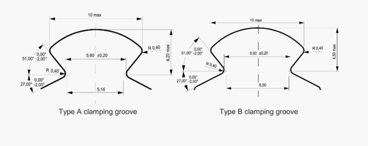
| Nominal cross section | Calculated cross section | Size and tolerance mm |
Angle and tolerance | |||||||||||
| mm² | mm² | A | B | C | D | E | K | R | G | H | ||||
| 120 | 121 | 12.90 | +0.13 | 12.90 | +0.26 | 9.76 | +0.20 | 7.24 | +0.29 | 6.80 | 4.35 | 0.40 | 27°±1° | 51°±1° |
| -0.13 | -0.26 | -0.20 | -0.14 | |||||||||||
| 150 | 151 | 14.40 | +0.14 | 14.40 | +0.29 | 9.71 | +0.19 | 7.24 | +0.29 | 6.80 | 4.00 | 0.40 | 27°±1° | 51°±1° |
| -0.14 | -0.29 | -0.19 | -0.14 | |||||||||||
|
Note:
|
||||||||||||||

| Type | Tensile streng th MPa |
Softening fraction | Elongation (unsoftened) |
Repeated bending | Number of turns (until disconnected) | Number of turns | Conductivity(20 °C)% IACS |
Resistivity (20°C) Ω · mm2/m |
Temperature coefficient of resistance | |
| Crack | Disconnect | |||||||||
| CT | ≥360 | - | ≥3.0% | ≥4 | ≥6 | ≥5 | ≥3 | ≥97 | ≤0.01777 | 0.00380 |
| CTA | ≥370 | ≥90% | ≥3.0% | ≥4 | ≥6 | ≥5 | ≥3 | ≥97 | ≤0.01777 | 0.00380 |
| CTS | ≥380 | ≥90% | ≥3.0% | ≥4 | ≥6 | ≥5 | ≥3 | ≥93 | ≤0.01854 | 0.00320 |
| CTSM | ≥430 | ≥90% | ≥3.0% | ≥4 | ≥6 | ≥5 | ≥3 | ≥80 | ≤0.02155 | 0.00320 |
| CTM | 0.00310 | |||||||||
| CTSH | ≥500 | ≥90% | ≥3.0% | ≥4 | ≥6 | ≥5 | ≥3 | ≥68 | ≤0.02535 | 0.00320 |
| CTMM | 0.00270 | |||||||||
| CTMH | ≥530 | ≥90% | ≥3.0% | ≥4 | ≥6 | ≥5 | ≥3 | ≥65 | ≤0.02653 | 0.00270 |
| CTCZ | ≥560 | ≥95% | ≥3.0% | ≥4 | ≥6 | ≥5 | ≥3 | ≥75 | ≤0.02299 | 0.00320 |