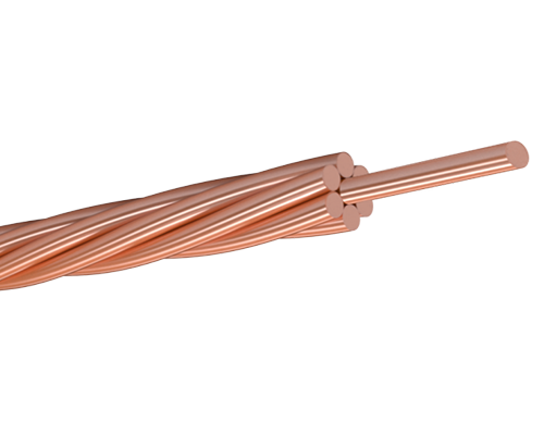
Catenary Wire (Copper alloy Stranded)for Electrified Railway
Conductor is concentrically stranded with bare copper or copper alloy wire.
| Nominal area of cross-section of stranded conductor | Construction (stranding and wire diameter) | Overall diameter of conductor (approx.) | Nominal mass per unit length | Resistance at 20 °C | Minimum breaking load | |
| Nominal | Max. | |||||
| mm² | number/mm | mm | kg/km | Ω/km | Ω/km | N |
| 10 | 7/1.35 | 4.05 | 89.82 | 1.788 | 1.829 | 3752 |
| 14 | 7/1.60 | 4.80 | 126.2 | 1.273 | 1.303 | 5267 |
| 16 | 3/2.65 | 5.70 | 148.3 | 1.082 | 1.106 | 6194 |
| 16 | 7/1.70 | 5.10 | 142.4 | 1.128 | 1.154 | 5946 |
| 25 | 7/2.10 | 6.30 | 217.3 | 0.7391 | 0.7563 | 9073 |
| 32 | 3/3.75 | 8.06 | 296.9 | 0.5405 | 0.5520 | 12400 |
| 32 | 7/2.46 | 7.38 | 298.2 | 0.5386 | 0.5497 | 12442 |
| 35 | 7/2.50 | 7.50 | 308.0 | 0.5215 | 0.5337 | 12860 |
| 50 | 7/3.00 | 9.00 | 443.5 | 0.3622 | 0.3706 | 18520 |
| 50 | 19/1.80 | 9.00 | 435.8 | 0.3727 | 0.3819 | 17700 |
| 70 | 7/3.55 | 10.65 | 621.1 | 0.2586 | 0.2646 | 25930 |
| 70 | 19/2.10 | 10.50 | 593.2 | 0.2738 | 0.2806 | 24090 |
| 95 | 19/2.50 | 12.50 | 840.7 | 0.1932 | 0.1980 | 34140 |
| 100 | 7/4.30 | 12.90 | 911.2 | 0.1763 | 0.1810 | 36540 |
| 120 | 19/2.80 | 14.00 | 1055 | 0.1540 | 0.1578 | 42830 |
| 125 | 19/2.90 | 14.50 | 1131 | 0.1436 | 0.1471 | 45940 |
| 150 | 19/3.20 | 16.00 | 1377 | 0.1180 | 0.1208 | 55940 |
| 150 | 37/2.25 | 15.75 | 1334 | 0.1233 | 0.1264 | 53880 |
| 185 | 19/3.55 | 17.75 | 1695 | 0.09582 | 0.09815 | 68860 |
| 185 | 37/2.50 | 17.50 | 1647 | 0.09981 | 0.1024 | 66490 |
| Nominal area of cross-section of stranded conductor | Construction (stranding and wire diameter) | Overall diameter of conductor (approx.) | Nominal mass per unit length | Resistance at 20 °C | Minimum breaking load | |
| Nominal | Max. | |||||
| mm² | number/mm | mm | kg/km | Ω/km | Ω/km | N |
| 12 | 3/2.30 | 4.95 | 112.4 | 1.743 | 1.780 | 6968 |
| 16 | 7/1.70 | 5.10 | 143.3 | 1.368 | 1.399 | 8883 |
| 22 | 7/2.00 | 6.00 | 198.3 | 0.9882 | 1.011 | 12290 |
| 25 | 7/2.10 | 6.30 | 218.7 | 0.8959 | 0.9171 | 13550 |
| 30 | 7/2.30 | 6.90 | 262.3 | 0.7469 | 0.7645 | 16260 |
| 35 | 7/2.50 | 7.50 | 309.9 | 0.6324 | 0.6471 | 19210 |
| 38 | 7/2.60 | 7.80 | 335.2 | 0.5847 | 0.5983 | 20780 |
| 45 | 7/2.90 | 8.70 | 417.0 | 0.4698 | 0.4809 | 24600 |
| 55 | 7/3.20 | 9.60 | 507.8 | 0.3859 | 0.3950 | 29950 |
| 70 | 19/2.10 | 10.50 | 596.8 | 0.3316 | 0.3403 | 35990 |
| 75 | 7/3.70 | 11.10 | 678.8 | 0.2887 | 0.2954 | 38010 |
| 95 | 19/2.50 | 12.50 | 845.9 | 0.2343 | 0.2400 | 51010 |
| 100 | 7/4.30 | 12.90 | 916.9 | 0.2138 | 0.2195 | 51160 |
| 120 | 19/2.80 | 14.00 | 1061 | 0.1862 | 0.1914 | 60890 |
| 125 | 19/2.90 | 14.50 | 1138 | 0.1739 | 0.1784 | 65310 |
| 150 | 19/3.20 | 16.00 | 1386 | 0.1428 | 0.1465 | 79530 |
| 150 | 37/2.25 | 15.75 | 1342 | 0.1493 | 0.1533 | 80490 |
| 180 | 19/3.50 | 17.50 | 1658 | 0.1196 | 0.1225 | 95140 |
| 180 | 37/2.50 | 17.50 | 1657 | 0.1209 | 0.1242 | 99330 |
| 200 | 19/3.70 | 18.50 | 1853 | 0.1068 | 0.1696 | 100900 |
| 240 | 19/4.00 | 20.00 | 2165 | 0.09153 | 0.09378 | 117900 |
| Nominal area mm2 |
Cross- sectional area mm2 |
Wire | Overall diameter mm |
Approx. mass per unit length kg/km |
Rated strength kN |
Current carrying capacity A |
|
| Number | Diameter mm |
||||||
| 10 | 10.02 | 7 | 1.35 | 4.1 | 90 | 4.02 | 90 |
| 16 | 15.89 | 7 | 1.70 | 5.1 | 143 | 6.37 | 125 |
| 25 | 24.25 | 7 | 2.10 | 6.3 | 218 | 9.72 | 160 |
| 35 | 34.36 | 7 | 2.50 | 7.5 | 310 | 13.77 | 200 |
| 50 | 49.48 | 7 | 3.00 | 9.0 | 446 | 19.84 | 250 |
| 48.35 | 19 | 1.80 | 9.0 | 437 | 19.38 | 250 | |
| 70 | 65.81 | 19 | 2.10 | 10.5 | 596 | 26.38 | 310 |
| 95 | 93.27 | 19 | 2.50 | 12.5 | 845 | 37.39 | 380 |
| 120 | 116.99 | 19 | 2.80 | 14.0 | 1060 | 46.90 | 440 |
| 150 | 147.11 | 37 | 2.25 | 15.8 | 1337 | 58.98 | 510 |
| 185 | 181.62 | 37 | 2.50 | 17.5 | 1649 | 72.81 | 585 |
| 240 | 242.54 | 61 | 2.25 | 20.3 | 2209 | 97.23 | 700 |
| 300 | 299.43 | 61 | 2.50 | 22.5 | 2725 | 120.04 | 800 |
| 400 | 400.14 | 61 | 2.89 | 26.0 | 3640 | 160.42 | 960 |
| 500 | 499.83 | 61 | 3.23 | 29.1 | 4545 | 200.38 | 1110 |
| Note: Current carrying capacity are valid up to a frequency of 60 Hz,a wind velocity of 0.6 m/s, an initial ambient temperature of 35 °C and a conductor temperature of 70°C. | |||||||
| Type | Section area mm2 |
Calculated overall diameter mm |
Structure | Single wire diameter mm |
Single wire | Stranded wire (Nominal) | ||||
| Min. tensile strength MPa |
Min. elongation % |
Min. breaking load kN |
Mass per unit length kg/km |
|||||||
| Nominal | Cross- sectional | Before stranding |
After stranding |
|||||||
| JT | 70 | 65.81 | 10.50 | 1×19 | 2.10 | 430 | 410 | 0.7 | 27.45 | 596 |
| JT | 95 | 93.27 | 12.50 | 1×19 | 2.50 | 430 | 410 | 0.7 | 38.54 | 844 |
| JT | 120 | 116.99 | 14.00 | 1×19 | 2.80 | 430 | 410 | 0.7 | 48.01 | 1059 |
| JT | 150 | 147.12 | 15.75 | 1×37 | 2.25 | 430 | 410 | 0.7 | 61.21 | 1334 |
| JTM | 25 | 24.25 | 6.30 | 1×7 | 2.10 | 520 | 494 | — | 11.98 | 218 |
| JTM | 35 | 34.36 | 7.50 | 1×7 | 2.50 | 520 | 494 | — | 16.97 | 309 |
| JTM | 35 | 34.93 | 7.65 | 1×19 | 1.53 | 520 | 494 | — | 17.26 | 316 |
| JTM | 50 | 49.48 | 9.00 | 1×7 | 3.00 | 520 | 494 | — | 24.44 | 446 |
| JTM | 50 | 48.35 | 9.00 | 1×19 | 1.80 | 520 | 494 | — | 23.88 | 438 |
| JTM | 70 | 65.81 | 10.50 | 1×19 | 2.10 | 520 | 494 | — | 32.51 | 596 |
| JTM | 95 | 93.27 | 12.50 | 1×19 | 2.50 | 520 | 494 | — | 46.08 | 844 |
| JTM | 120 | 116.99 | 14.00 | 1×19 | 2.80 | 520 | 494 | — | 57.79 | 1059 |
| JTM | 150 | 147.12 | 15.75 | 1×37 | 2.25 | 520 | 494 | — | 72.67 | 1334 |
| JTMH | 25 | 24.25 | 6.30 | 1×7 | 2.10 | 620 | 589 | — | 14.28 | 218 |
| JTMH | 35 | 34.36 | 7.50 | 1×7 | 2.50 | 620 | 589 | — | 20.24 | 309 |
| JTMH | 35 | 34.93 | 7.65 | 1×19 | 1.53 | 620 | 589 | — | 20.57 | 316 |
| JTMH | 50 | 49.48 | 9.00 | 1×7 | 3.00 | 620 | 589 | — | 29.14 | 446 |
| JTMH | 50 | 48.35 | 9.00 | 1×19 | 1.80 | 620 | 589 | — | 28.48 | 438 |
| JTMH | 70 | 65.81 | 10.50 | 1×19 | 2.10 | 620 | 589 | — | 38.76 | 596 |
| JTMH | 95 | 93.27 | 12.50 | 1×19 | 2.50 | 620 | 589 | — | 54.94 | 844 |
| JTMH | 120 | 116.99 | 14.00 | 1×19 | 2.80 | 620 | 589 | — | 68.91 | 1059 |
| JTMH | 150 | 147.11 | 15.75 | 1×37 | 2.25 | 620 | 589 | — | 86.65 | 1334 |
| JTMM | 70 | 65.81 | 10.50 | 1×19 | 2.10 | 620 | 589 | — | 38.76 | 596 |
| JTMM | 95 | 93.27 | 12.50 | 1×19 | 2.50 | 620 | 589 | — | 54.94 | 844 |
| JTMM | 120 | 116.99 | 14.00 | 1×19 | 2.80 | 620 | 589 | — | 68.91 | 1059 |
| JTMM | 150 | 147.11 | 15.75 | 1×37 | 2.25 | 620 | 589 | — | 86.65 | 1334 |
| JTCZ120 | 120 | 119.75 | 14.21 | 1×37 | 2.03 | 520 | 494 | — | 59.16 | 1092 |