APPLICATION
Medium voltage cables for distribution networks. They are suitable for laying Indoor, tunnel, cable trench, shaft or buried laying, The cable can withstand mechanical external forces and a certain tensile force, it widely used in transformer stations, electric power plants and industrial plants.
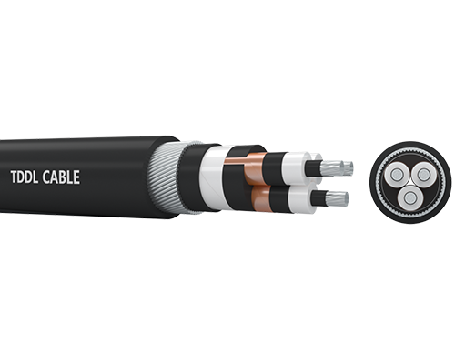
CONSTRUCTION
● Conductor :Copper, class 2, circular compacted conductors
● Conductor screen:Non-metallic,semi-conducting compound
● Insulation:Cross-Linked polyethylene XLPE
● Insulation screen:Non-metallic,semi-conducting compound
● Metallic screen:Copper tape
● Inner sheath:Polyvinyl chloride PVC
● Armour: Non-magnetic steel tape
● Outer sheath: Polyvinyl chloride PVC
MAIN CHARACTERRISTICS
Good electrical and mechanical properties. Minimal dielectric loss, high insulation resistance. The PVC outer sheath allows adequate resistance to grease, oil and abrasion.
SPECIFICATION
IEC 60228 Conductors of insulate cables.
IEC 60502-2 Power cables with extruded insulation and their accessories for rated voltages from 1 kV(Um=1.2kV) up to 30kV(Um=36kV) - Part 2:Cables for rated voltages of 6kV(Um=7.2kV) and 30 kV(Um=36kV)